中文
中文
-
Shipping Containers
- Container Parts
- Roof Panel
- Side Panel
- Front End Panel
- Door Panel
- Front Corner Post
- Rear Corner Post (Outer/Inner)
- Cross Member
- Bottom Side Rail
- Top Side Rail
- Door Sill
- Front Bottom Rail
- Top End Rail
- Door Header Upper/Lower
- Door Rail
- Floor Spacer
- Angle
- Top/Bottom End Rail
- Door Edge Member
- Door Sealing
- Door Frame Profile
- Door Lining
- Door Hardwares
- Door Gasket
- Side Panel/Lining
- T-Floor
- Roof Panel/Lining
- Cross Member
- Bottom Side Rail
- Top Side Rail
- Ledge PVC
- Kazoo Drain
- Auto Drain
- Alu Tube
- Auto Drain Center Part
- PVC Drain Pipe
- PVC Plugs f. Drain with Ring and Steel Wire
- Door Screw
- Door Screw Nut
- Door Screw Rubber
- Tapping Screw
- Stainless Blind Rivet
- Lashing Ring
- CSC Plate
- Welding Wire
- Tapping Screw Bit
- Vehicle Parts
- Ship Supplies
- 00. Provisions
- 11. Welfare Items
- 15. Cloth & Linen Products
- 17. Tableware & Galley Utensils
- 19. Clothing
- 21. Rope & Hawsers
- 23. Rigging Equipment & General Deck Items
- 27. Painting Equipment
- 31. Safety Protective Gear
- 33. Safety Equipment
- 35. Hose & Couplings
- 37. Nautical Equipment
- 39. Medicine
- 45. Petroleum Products
- 47. Stationery
- 49. Hardware
- 51. Brushes & Mats
- 55. Cleaning Material & Chemicals
- 59. Pneumatic & Electrical Tools
- 61. Hand Tools
- 63. Cutting Tools
- 65. Measuring Tools
- 69. Screws & Nuts
- 75. Valves & Cocks
- 77. Bearings
- 79. Electrical Equipment
- 81. Packing & Jointing
- 85. Welding Equipment
- 87. Machinery Equipment
- Vehicles
- Lashing Tools
- Logistics Tools
Container PartsIntroduction of Dry Container Spare Parts: CIMC EquilinkJun 15,2020All dry shipping containers are made up of primary structural components such as the wall, roof, and floor panels. Corten steel is mainly used in the whole manufacturing process for these main structures but the thickness and size may vary in size and shape.
1. Corner Fittings:
Internationally standard fitting (casting) located at the eight corners of the container structure to provide means of handling, stacking and securing containers. Specifications are defined in ISO 1161.
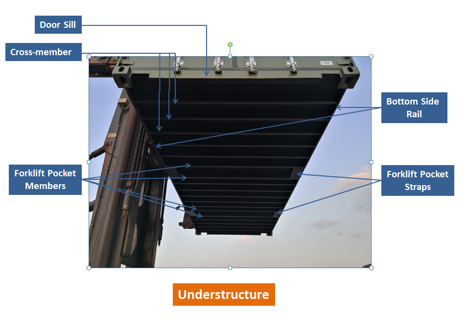
2. Base Frame:
The base frame will be composed of two (2) bottom side rails, a number of cross-members and a pair of fork pockets, which are welded together as a sub-assembly.
2.1. Bottom Side Rail: Longitudinal structural member situated at the bottom edge of each side of the container and joined to the corner fittings to form a part of the understructure.
2.2. Cross-member: Lateral structural member attached to the bottom side rails that support the flooring.
2.3. Forklift Pocket: Reinforced tunnel (installed in pairs) situated transversely across the understructure and providing openings in the bottom side rails at ISO prescribed positions to enable either empty capacity or empty and loaded capacity container handling by forklift equipment.
2.4. Forklift Pocket Strap: The plate welded to the bottom of each forklift pocket opening or part of bottom side-rail. The forklift pocket strap is a component of the forklift pocket.
2.5. Gooseneck Tunnel: Recessed area in the forward portion of the understructure to accommodate transport by a gooseneck chassis. This feature is more common in forty foot and longer containers.
2.6. The Floor Boards: The floor consists of plywood. The plywood is treated with wood preservative containing according to the latest requirement of the Commonwealth Department of Health, Australia.
3. Front End:
The front end is composed of corrugated end wall and front end frame, which are welded together as a sub-assembly.
3.1. Front End Wall: The front end wall is composed of steel sheet fully vertically corrugated into trapezium section, butt joint together to form one panel by means of automatic welding.
3.2. Front End Frame: The structural assembly at the rear (door end) of the container consisting of the door sill and header joined at the rear corner fittings to the rear corner posts to form the door opening.
3.3. Front Sill: The front sill is made of special “C” section steel pressed with vertical webs as the stiffener.
3.4. Corner Post: Vertical structural member located at the four corners of the container and to which the corner fittings are joined.
3.5. Front Header: The front header is constructed single structure of 4.0 mm thickness; "Z" pressed steel plate with reinforcements at each top corner. The upper part is extended inwards of the container certain distance with full width from front part of top corner fitting.
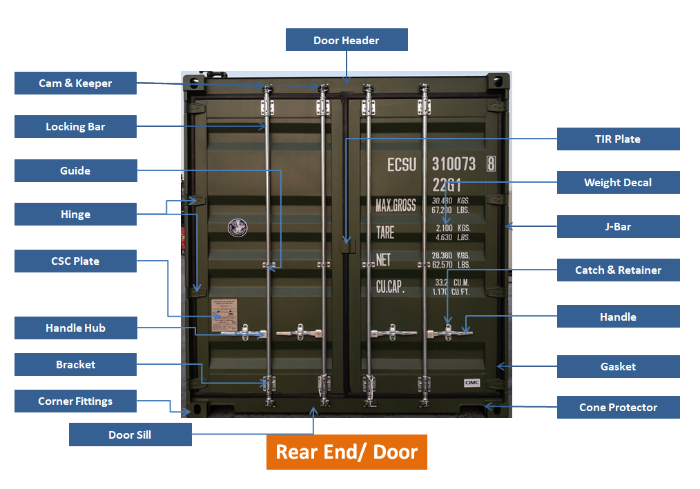
4. Rear End:
4.1. Door Sill: Lateral structural member at the bottom of the door opening and joined to the corner fittings in the door end frame.
4.2. Corner Post
4.3. Door Header: Lateral structural member situated over the door opening and joined to the corner fittings in the door end frame.
4.4. Door Systems:
Doors will consist of two door leaves, each leaf with two locking devices, four hinges and pins, seal gaskets and the door holders. The doors will be installed by hinge pins to the rear end frame and capable of swinging about 270 degrees.
4.4.1. Door Leaves: Each leaf consists of door panel, steel door frame which consists of horizontal (upper & lower) and vertical (inner & outer) members. They are welded together to form the rectangular door leaves. The doors are so arranged that the left leaf cannot be opened without displacement of the right leaf.
4.4.2. Hinges and Pins: Four reinforced forged hinges, providing with bushed hole, are welded to each door leaf. Each door is installed by hinge pins, washers and bushings.
4.4.3. Locking Devices: Two locking bars are of steel tube with handles, anti-racking rings and cam ends, and fixed to each door leaf with bolts / nuts and six huck bolts at TIR locations, by top and bottom bearing brackets and bar guide brackets. The bars are suspended in bearing brackets with bush of self-lubricating synthetic material. Cam-keepers are welded to the door header and sill.
4.4.4. Door Holder and Receptacle: A door holder per door, made of mixed nylon rope, is tied to the center side locking rod & the receptacle (door hook) is welded to each bottom side rail to remain the door at the open position.
4.4.5. Seal Gaskets: The black door seal gaskets are of "J-C" type EPDM rubber. They are attached to the door frame with stainless steel rivets and retainer strips. The gasket is set with adhesive sealant on the back.
4.4.6. Shim: The E.P.D.M shim will be placed over the holes on the door for fastener (except under large bearing brackets).
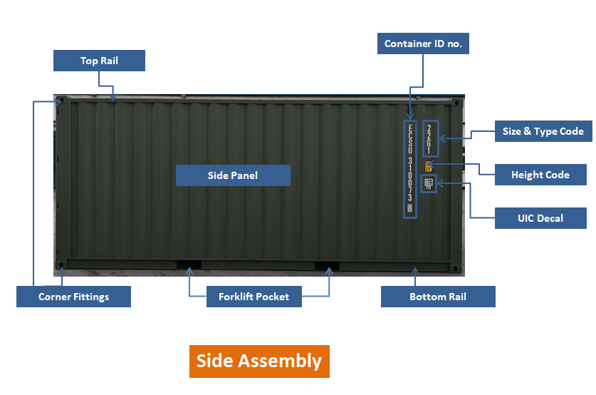
5. Side Wall Assembly:
5.1. Top Side Rails: Longitudinal structural member situated at the top edge of each side of the container and joined to the corner fittings of the end frames.
5.2. Side Walls: Each side wall will be composed of a number of sheets for the intermediate (inner) parts and outer panels at each end of side wall, fully vertically corrugated into trapezium section, butt welded together to form one panel by automatic welding.
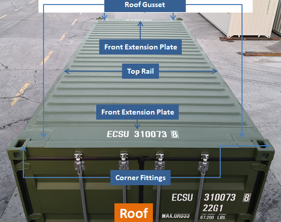
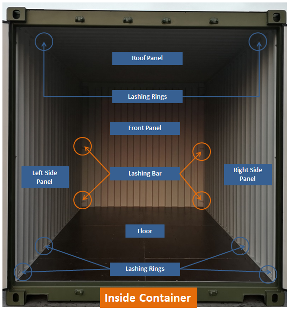
6. Roof: The roof will be constructed by several die-stamp corrugated steel sheets with a certain upwards camber at the center of each trough and corrugation, these sheets are butt jointed together to form one panel by automatic welding.
6.1. Roof Panel:
6.2. Roof reinforcement plate: Four 3.0mm thickness, reinforcement plates are mounted around the four corner fittings.
7. Other:
7.1. Lashing Rings: Lashing rings are welded to each bottom and top side rail at corresponding recessed area of side wall.
7.2. Sill Cut-Outs: 200 x 75 x 9mm channel section steel recesses are provided in each end of rear and front sills adjacent to the bottom fitting to prevent damage due to any twist-lock misalignment.
7.3. Ventilators: Different number of ventilators are added on the container as per the requirement from the customers
7.4. Decals: Container also may have different logos or signs as per the preference from the customers apart from ISO marking decals.
7.5. CSC Plate: The containers will bear marking plate in accordance with the requirements of the Classification Authorities and owner.
CIMC Equilink offers all types of parts that are being used to repair or manufacture the containers. For more info please contact us at info.equilink@cimc.com.
Share:


Quick Quote
Contact UsHutai Road, No. 6415 Baoshan District, Shanghai China
Tel: +86 21 6686 7007
Fax: +86 21 6686 7007
Company Mobile: +86 17316368719
Email: info.equilink@cimc.com


 Copyright © 2019 CIMC Equilink
- Container Parts